MACOM UPDATES
- Articles
Non-Linear Transmission Line Comb Generators Part-2: Solutions to the Low Phase Noise Problem
Overview
In this two part series from MACOM, we will delve into Non-Linear Transmission Line (NLTL) Comb Generators. In part 1 we considered the phase noise problem and introduced a potential solution to the problem. In this second part of the blog series, we will explore NLTL comb generation, compare it to its predecessor comb generation using Step Recovery Diodes and see how the NLTL comb generation approach can enable improved sensitivity and lower bit error rates in communication systems.
SRD Comb Generation
Many systems require signals at frequencies which are not easily generated or in some cases impossible to generate directly. The widely-employed mitigation strategy has been to apply a locally-generated, low-frequency signal known as the ‘fundamental frequency’ to a circuit containing nonlinear impedance, which translates energy from the fundamental signal frequency to its harmonics. Step recovery diodes (SRDs) have been used extensively to multiply the frequency of a signal. The step recovery diode is a pn junction device, typically silicon, comprising 3 layers: the p layer anode, a lightly-doped n layer and a heavily-doped n layer, the latter two of which comprise the cathode of the diode.
The SRD goes into conduction when the positive (forward bias) alternation of an input signal is applied. Charge carriers (holes) from the p layer and the n layers (electrons) flow, which produces low diode impedance. Immediately after the polarity of the input signal reverses to the negative-bias polarity, the population of these charge carriers is as large as it was under forward bias, so the diode’s impedance remains low. A non-zero interval is required for the charge carriers to be conducted out of the diode.
When the population of the free charge carriers is small, the recombination of holes and electrons becomes the dominant mechanism responsible for the impedance of the diode. When recombination is completed, the diode’s impedance has completed the transition from its low value to its maximum value. In effect, the diode current “snaps off”. In Figure 1 below, the typical current versus time plot is shown.
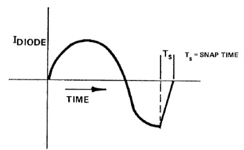
Figure 1 Typical Current vs. Time Plot
A typical step-recovery-diode frequency multiplier circuit is shown in Figure 2
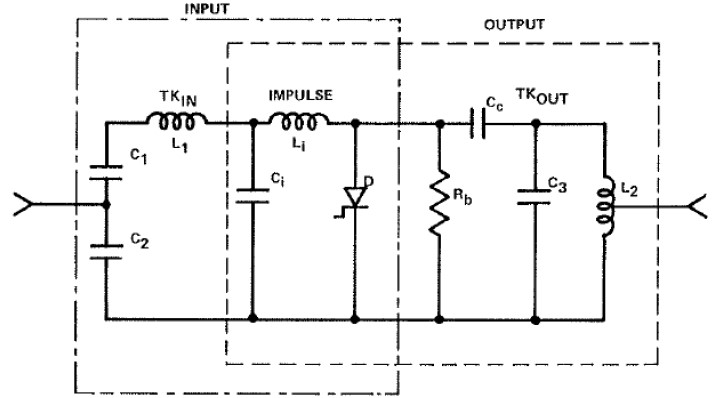
Figure 2 Typical Step-Recovery Diode Frequency Multiplier Circuit
The RF current which flows through the SRD, D, also flows through the inductor Li. As the SRD current snaps off, the current through inductor Li also very rapidly decreases to zero. This sudden decrease in current through the inductor creates an impulse-like voltage waveform which is rich in even and odd harmonics.
Recombination is a stochastic process. Recombination can only occur when a hole and an electron pair are in “the right place at the right time”. It is not difficult to imagine that this process does not occur identically, cycle after input cycle, but rather occurs with random variations. This produces jitter of the impulse-like waveform in the time domain, which is equivalent to phase noise in the frequency domain.
NLTL Comb Generation
MACOM’s family of nonlinear transmission line (NLTL) comb generators produce harmonics of an input signal in an entirely different manner than that employed in the SRD comb generator.
Recall that the equivalent circuit of a transmission line is composed of a ladder network of series inductors and shunt capacitors. This structure is shown below.
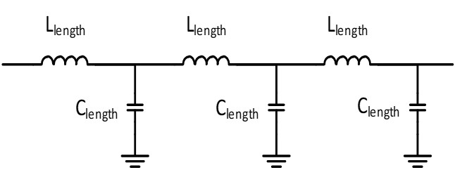
In a nonlinear transmission line comb generator, the shunt capacitors are replaced with Schottky junction varactor diodes. The capacitance of a varactor diode is inversely proportional to the reverse-bias voltage across the diode. At small reverse-bias signal voltage, the varactor diode produces maximum capacitance. As the reverse voltage increases in magnitude, the capacitance of the varactors decreases in a nonlinear manner.
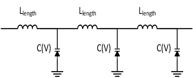
The capacitance of the Schottky varactors is a virtually instantaneous function of the amplitude of an incident signal. As an input signal propagates through the transmission line structure, the phase velocity of the lower-voltage portion of its negative alternation is lower than that of its higher-voltage portion due to the higher varactor capacitance produced by the Schottky varactors.(3) Cascaded L-C sections of the transmission structure cause a portion of the waveform to be increasingly vertical, as plotted versus time, as additional L-C sections are traversed. This distortion of the waveform produces harmonics of the fundamental input signal frequency.
Schottky varactor diodes are utilized in the NLTL comb generator because they are majority carrier devices - there are no minority charge carriers in Schottky diodes so there is no stochastic carrier recombination to produce flicker noise and other random fluctuations which are unavoidable in pn junction devices like SRDs. Thus an NLTL comb generator produces much less additive phase noise than does a SRD comb generator, by as much as 10 to 15 dB. Figure 3 below compares the additive phase noise for offset frequencies up to 1 MHz for the MLPNC-7103S1-SMT580 NLTL comb generator at 12 GHz output frequency when driven with a 500 MHz input signal at 22 dBm input power versus the output of a SRD comb generator with at the same output frequency with the same input signal conditions.
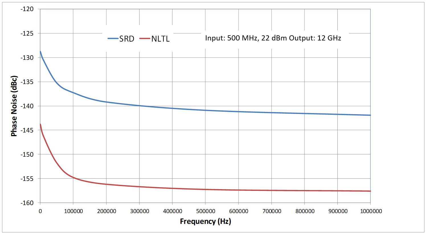
Figure 3
Conclusion
MACOM offers a family of low-phase-noise NLTL comb generators in surface mount or connectorized modules which have best-in-class phase noise, conversion loss and frequency coverage performance. These products enable significantly improved sensitivity in radar and communications receivers and lower bit error rates in vector-modulated systems. For more information on MACOM’s Comb Generators: https://www.macom.com/products/frequency-generation/nltl-gaas-comb-generators
References
3. Breitbarth, J., “Design and Characterization of Low Phase Noise Microwave Circuits”, University of Colorado, 2006